Specifications
| Technical data | |
|---|---|
| Measuring quantity | Standard flow velocity wN based on standard conditions 1) Temperature of medium TM |
| Measured medium | Clean a or nitrogen, additional gases on request |
| Measuring range wN | 0 … 1 / 2.5 / 10 m/s |
| Max. display range wN | +10 % above measuring range |
| Lower detection limit wN | 0.1 m/s |
| Measuring range TM | -20 … +70 °C |
| Measuring accuracy | |
| Standard wN | ±(3 % of measured value + 0.05 m/s) 2) |
| High precision (optional) wN | ±(1 % of measured value + 0.04 m/s) 2) |
| Response time (t90) wN | 15 s |
| Temperatur TM (wN > 0.3 m/s) | ±1 K (10 … 30 °C); ±2 K (remaining measuring range) |
| Operating temperature | |
| Sensor | 0 … 60 °C |
| Storage temperature | -20 … +85 °C |
| Material | |
| Sensor head | Stainless steel 1.4404 |
| Sensor tube | Stainless steel 1.4404 |
| Plug connector, nut screw | Stainless steel 1.4404 |
| Light ring | PC |
| General data | |
| Humidity | Measuring mode: Non-condensing (< 95 % RH) |
| Operating pressure (max.) | Atmospheric (700 … 1,300 hPa) |
| Supply voltage | 24 V DC ± 10 % |
| Current consumption | tbd |
| Analog outputs wN & TM | 0 … 10 V (RL ≥ 10 kΩ; short-circuit protected) 4 … 20 mA (RL ≤ 300 Ω>br> CL ≤ 10 nF |
| Error signal | Only with current interface: 2 mA (according to NAMUR NE43) |
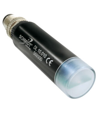
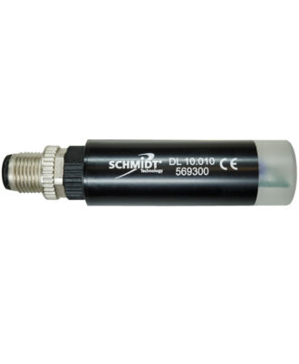
| Electrical connection | Plug-in-connector M9, male, 7-pin (shielded), screwed |
| Maximum cable length | Voltage interface / current interface: 100 m Voltage mode: Use AGND and RL ≥ 10 k (mass offset) |
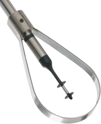
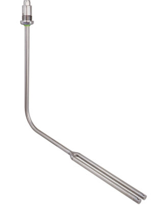
| Mounting position | Straight: ±3° relative to flow direction (unidirectional) Angled: Vertical downdraft flow (per design |
| Protection type | IP65; electrical connector: IP67 (with correctly attached cable) |
| Protection class | III (SELV or PELV) |
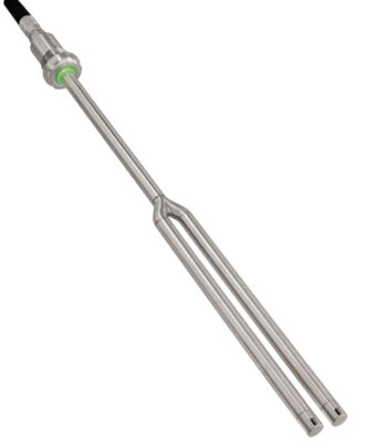
| Sensor length | Angled: 150/270 mm (vertical) x 300 mm (horizontal) Straight: 300 mm |
| Weight | Approx. 280 g (angled design with 270 mm x 300 mm) |
| Digital interface | Modbus (RTU); RS485 (EIA-485), 2-wire, 3.3 V |
1) Standard conditions: TN = 20 °C and pN = 1,013.25 hPa
2) Related to adjustment reference; “fmr” = full measuring range
Subject to technical changes.