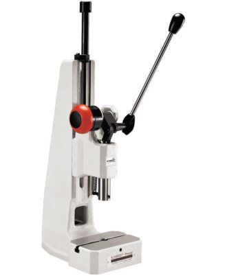
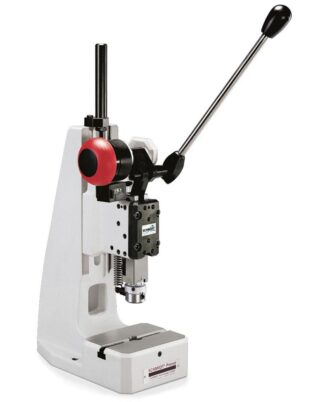
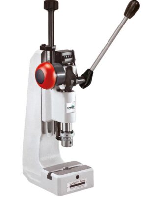
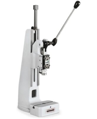
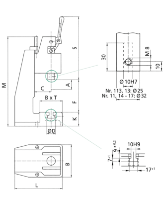
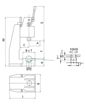
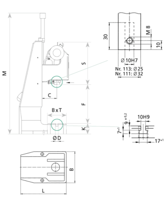
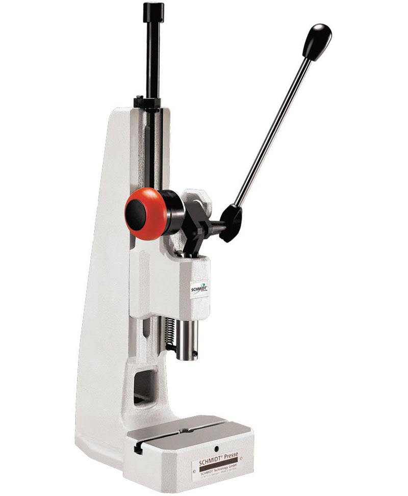
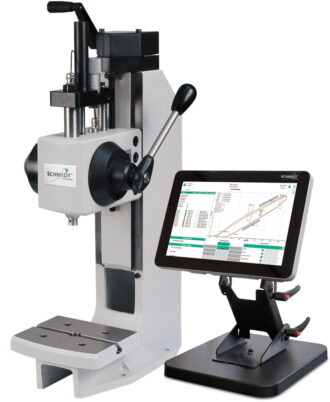
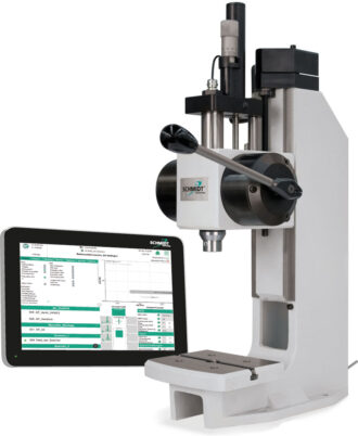
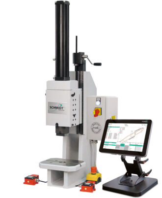
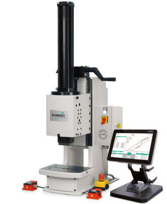
5 à 15 kN données techniques
| Press type | | | 13
13F | 13R
13RF | 11
11F | 11R
11RF | 15
15F | 15R
15RF | 14
14F | 14R
14RF | 16
16F | 16R
16RF | 17
17F |
|---|
| Press head type | | | 13-40
13F-35 | 13R-40
13RF-35 | 11-45
11F-35 | 11R-45
11RF-35 | 11-45
11F-35 | 11R-45
11RF-35 | 11-60
11F-50 | 11R-60
11RF-50 | 11-60
11F-50 | 11R-60
11RF-50 | 11-20
11F-20 |
| Nominal force | | kN | 5 | 5 | 12 | 12 | 12 | 12 | 12 | 12 | 12 | 12 | 15 |
| Working stroke5) | A | mm | 40
35 | 40
35 | 45
35 | 45
35 | 45
35 | 45
35 | 60
50 | 60
50 | 60
50 | 60
50 | 20
20 |
| Throat depth | C | mm | 65 | 65 | 86 | 86 | 86 | 86 | 86 | 86 | 86 | 86 | 86 |
| Press head height | S | mm | 385
400 | 385
400 | 520
540 | 520
540 | 520
540 | 520
540 | 500
520 | 500
520 | 500
520 | 500
520 | 620
640 |
Max. Weight of upper tool 3)
standard / reinforced spring | | kg | 1.2 / 3.5
1.5 / 3 | 1.2 / 3.5
1.5 / 3 | 2 / 4.5
2.5 / 6 | 2/4
2/6 | 2 / 4.5
2.5 / 6 | 2/4
2/6 | 1.5 / 2.5
2/5 | 1.5 / 2.5
1.5 / 4 | 1.5 / 2.5
2/5 | 1.5 / 2.5
1.5 / 4 | 2.5 / -
2.5 / - |
| Working height 4) | F | | | | | | | | | | | | |
|---|
| Stand No. 13 | | mm | 65 – 180
40 – 155 | 66 – 180
40 – 155 | | | | | | | | | |
| Stand No. 3 | | mm | | | 75 – 210
50 – 185 | 75 – 210
50 – 185 | | | 90 – 220
65 – 195 | 90 – 220
65 – 195 | | | 65 – 200
50 – 185 |
| Frame No. 5 | | mm | | | | | | | | | | | 65 – 315
50 – 300 |
| Frame No. 2 | | mm | | | | | 100 – 345
80 – 325 | 100 – 345
80 – 325 | | | 110 – 360
85 – 335 | 110 – 360
85 – 335 | |
| Frame No. 2-600 ○ | | mm | | | 200 – 585
175 – 560 | 200 – 585
175 – 560 | 200 – 585
175 – 560 | 200 – 585
175 – 560 | 210 – 595
185 – 570 | 210 – 595
185 – 570 | 210 – 595
185 – 570 | 210 – 595
85 – 570 | 200 – 585
175 – 560 |
| Frame No. 2-1000 ○ | | mm | | | 330 – 1020
305 – 1000 | 330 – 1020
305 – 1000 | 330 – 1020
305 – 1000 | 330 – 1020
305 – 1000 | 340 – 1030
315 – 1010 | 340 – 1030
315 – 1010 | 340 – 1030
315 – 1010 | 340 – 1030
315 – 1010 | 330 – 1020
305 – 1000 |
| Weight | | approx. kg | 12 | 13 | 23 | 24 | 29 | 29 | 24 | 24 | 29 | 29 | 23 |
| Accessories | 13
13F | 13R
13RF | 11
11F | 11R
13RF | 15
15F | 15R
15RF | 14
14F | 14R
13RF | 16
16F | 16R
16RF | 17
17F |
|---|
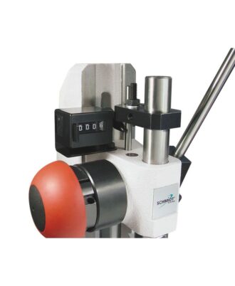
| Mechanical counter | ○ | ○ | ○ | ○ | ○ | ○ | ○ | ○ | ○ | ○ | ○ |
| Projection adaptation (total projection) 111 mm, 131 mm | | | ○ | ○ | ○ | ○ | ○ | ○ | ○ | ○ | |
Additional table top suitable for
projection adaptation | | | ○ | ○ | ○ | ○ | ○ | ○ | ○ | ○ | ○ |
| Stop clamp 2) | ○
○ | ○
○ | ●
● | ●
● | ●
● | ●
● | ○
○ | ○
○ | ○
○ | ○
○ | ●
● |
| Shortening the working stroke | 10 | 10 | 10 | 10 | 10 | 10 | 10 | 10 | 10 | 10 | 10 |
| Stand overview | Press type | Stand height
M (mm) | Table size
W x D (mm) | Table bore
D (Ø mm) | Table height
K (mm) | Footprint
W x L (mm) |
|---|
| No. 13 | 13 | 475 | 110 x 80 | 20 H7 | 46 | 110 x 185 |
| No. 3 | 11, 14, 17 | 540 | 150 x 110 | 20 H7 | 60 | 150 x 260 |
| No. 5 | 17 | 536 | 185 x 110 | 20 H7 | 60 | 185 x 275 |
| No. 2 | 15, 16 | 700 | 185 x 110 | 20 H7 | 60 | 185 x 280 |
| No. 2-600 | 11, 14, 15, 16, 17 | 974 | 200 x 160 | 20 H7 | 98 | 200 x 290 |
| No. 2-1000 | 12, 14, 15, 16, 17 | 1410 | 200 x 160 | 20 H7 | 98 | 200 x 290 |
| Options |
|---|
| ● Standard at no extra charge ○ variant with surcharge |
| 1) Adjustment of the locking position possible on request |
| 2) Stroke shortened by 10 mm for variant at extra cost |
| 3) Weight was determined in hand lever position 45 ° forward (guide values) with standard stroke (not special stroke) |
| 4) Typical values; can deviate by ±3 mm due to casting and manufacturing tolerances |
5) Stroke adjustable with stop clamp (in the scope of delivery) | | Special designs |
|---|
| Nickel-plated version for a surcharge, press frame, cast parts and table top chemically nickel-plated, steel parts burnished, aluminum parts anodized, polished components bright |
| Special painting RAL colors |
| Special table bores and special ram bores on request |
-------------------------------
| Type de presse | | | 13
13F | 13R*
13RF | 11
11F | 11R*
11RF | 15
15F | 15R*
15RF | 14
14F | 14R*
14RF | 16
16F | 16R*
16RF | 17
17F |
|---|
| Type de tête | | | 13-40
13F-35 | 13R-40
13RF-35 | 11-45
11F-35 | 11R-45
11RF-35 | 11-45
11F-35 | 11R-45
11RF-35 | 11-60
11F-50 | 11R-60
11RF-50 | 11-60
11F-50 | 11R-60
11RF-50 | 11-20
11F-20 |
| Force nominale | | kN | 5 | 5 | 12 | 12 | 12 | 12 | 12 | 12 | 12 | 12 | 15 |
| Course de travail | A | mm | 40
35 | 40
35 | 45
35 | 45
35 | 45
35 | 45
35 | 60
50 | 60
50 | 60
50 | 60
50 | 20
20 |
| Col de cygne | C | mm | 65 | 65 | 86 | 86 | 86 | 86 | 86 | 86 | 86 | 86 | 86 |
| Hauteur de tête | S | mm | 385
400 | 385
400 | 520
540 | 520
540 | 520
540 | 520
540 | 500
520 | 500
520 | 500
520 | 500
520 | 620
640 |
Poids max. outil haut 3)
standard / ressort renforcé | | kg | 1,2 / 3,5
1,5 / 3 | 1,2 / 3,5
1,5 / 3 | 2 / 4,5
2,5 / 6 | 2 / 4
2 / 6 | 2 / 4,5
2,5 / 6 | 2 / 4
2 / 6 | 1,5 / 2,5
2 / 5 | 1,5 / 2,5
1,5 / 4 | 1,5 / 2,5
2 / 5 | 1,5 / 2,5
1,5 / 4 | 2,5 / -
2,5 / - |
| Hauteur de travail 4) | F | | | | | | | | | | | | |
|---|
| Bâti No. 13 | | mm | 65 – 180
40 – 155 | 66 – 180
40 – 155 | | | | | | | | | |
| Bâti No. 3 | | mm | | | 75 – 210
50 – 185 | 75 – 210
50 – 185 | | | 90 – 220
65 – 195 | 90 – 220
65 – 195 | | | 65 – 200
50 – 185 |
| Bâti No. 2 | | mm | | | | | 100 – 345
80 – 325 | 100 – 345
80 – 325 | | | 110 – 360
85 – 335 | 110 – 360
85 – 335 | |
| Bâti No. 2-600 ○ | | mm | | | 200 – 585
175 – 560 | 200 – 585
175 – 560 | 200 – 585
175 – 560 | 200 – 585
175 – 560 | 210 – 595
185 – 570 | 210 – 595
185 – 570 | 210 – 595
185 – 570 | 210 – 595
85 – 570 | 200 – 585
175 – 560 |
| Bâti No. 2-1000 ○ | | mm | | | 330 – 1020
305 – 1000 | 330 – 1020
305 – 1000 | 330 – 1020
305 – 1000 | 330 – 1020
305 – 1000 | 340 – 1030
315 – 1010 | 340 – 1030
315 – 1010 | 340 – 1030
315 – 1010 | 340 – 1030
315 – 1010 | 330 – 1020
305 – 1000 |
| Poids | | env. kg | 12 | 13 | 23 | 24 | 29 | 29 | 24 | 24 | 29 | 29 | 23 |
| Accessoires | 13
13F | 13R*
13RF | 11
11F | 11R*
13RF | 15
15F | 15R*
15RF | 14
14F | 14R*
13RF | 16
16F | 16R*
16RF | 17
17F |
|---|
| Compteur mécanique | ○ | ○ | ○ | ○ | ○ | ○ | ○ | ○ | ○ | ○ | ○ |
Adaptation col de cygne (col de cygne total)
111 mm, 131 mm | | | ○ | ○ | ○ | ○ | ○ | ○ | ○ | ○ | |
| Table de presse supplém. correspondant à l'adaptation col de cygne | | | ○ | ○ | ○ | ○ | ○ | ○ | ○ | ○ | ○ |
| Plaquette de serrage 2) | ○
○ | ○
○ | ●
● | ●
● | ●
● | ●
● | ○
○ | ○
○ | ○
○ | ○
○ | ●
● |
| Aperçu des bâtis | Type de presse | Hauteur de bâti
M (mm) | Dimension table
B x T (mm) | Alésage de table
D (Ø mm) | Hauteur de table
K (mm) | Encombrement
B x L (mm) |
|---|
| No. 13 | 13 | 475 | 110 x 80 | 20H7 | 46 | 110 x 185 |
| No. 3 | 11, 14, 17 | 540 | 150 x 110 | 20H7 | 60 | 150 x 260 |
| No. 2 | 15, 16 | 700 | 185 x 110 | 20H7 | 60 | 185 x 280 |
| No. 2-600 | 11, 14, 15, 16, 17 | 974 | 200 x 160 | 20H7 | 98 | 200 x 290 |
| No. 2-1000 | 12, 14, 15, 16, 17 | 1410 | 200 x 160 | 20H7 | 98 | 200 x 290 |
| Options |
|---|
| ● Série sans supplément de prix ○ Variantes avec supplément de prix |
| 1) Modification possible de la position d'arrêt sur demande |
| 2) Réduction de course de 10 mm pour la variante en option |
| 3) Le poids a été déterminé avec un levier positionné à 45° vers l'avant (valeurs indicatives) et pour une course standard (hors courses spéciales) |
| 4) Les valeurs peuvent varier de ±3 mm en raison des tolérances de fonderie et de finition |
| Versions spéciales |
|---|
| Version nickelée avec supplément de prix, bâti de presse, pièces moulées en fonte et table de presse nickelées, pièces en acier brunies, pièces en aluminium anodisées, composants rectifiés brillants |
| Peinture spéciale teintes RAL |
| Sur demande, alésages spéciaux pour table et coulisseau |

